|
|
||||||
| image | activities | contacts | links | italiano | ||||||
|
6.
international festival for architecture in video |
||||||
|
introduction
program -dates -authors -events partners credits previous editions mailto |
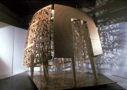 It is Objectile’s aim to develop all procedures, both software and hardware, that will make Digital Architecture a reality at an affordable cost for small architecture practice and average customers. After a series of experimentations at the scale of objects, furniture and sculpture, Objectile developed a series of wooden decorative panels as basic building components. Objectile now focuses on small scale architecture where current state of the art in software is just starting to make it possible to contemplate a fully digital architecture. The Semper Pavillion presented in Archilab (1999) was a first piece of digital architecture where everything, from design procedures up to the manufacturing process, was generated on the same software platform. Complex interlacings and undulated surfaces were algorithmically generated and then manufactured on a numerical command router up to the very last detail: i.e. the control of the tool path which creates the texture on the surfaces. But such a small a piece of architecture required two month’s work for the office. Furthermore, should we have to change the design of the pavilion, most of the operations would have to be repeated, without significant sparing of time. Hence we moved towards fully associative design and manufacture which appears to be the key issue of digital architecture. In an associative architecture, design procedures rely on a limited number of geometrical and numerical parents which can be easily modified and then regenerate the whole design of the building as well as its manufacturing programs. In a limited scale architecture, like the Philibert De L’Orme Pavillion (presented in Batimat 2001), associativity means to establish a seamless set of relations between a few control points and the 765 machining programs needed to manufacture it on a numerical command router. Due to the double curvature cladding of a non orthogonal structure, every single piece is different: the 12 structural elements, the 45 curved panels machined on both sides as well as the 180 connecting pieces. If only, the automatic naming of the pieces is already an issue. So let us check what the state of the art was at the time of the manufacture of this second pavilion and examine why Objectile keeps focusing on software development. Projective architectural skeleton The general architecture of Philibert De L’Orme is a projective cube whose three sets of ridges are made to converge in the finite space. By moving those three vanishing points, the whole of the Pavillion is to be reconfigured down to the very last technical detail. Very much in the same way as Philibert De L’Orme conceived his famous “trompes” as a general system of two intersecting conical shapes (1), this pavilion was designed as an homage to the inventor of stereotomy which would, later on, be systematized by another French architect: Girad Desargues. It is very important to remember that projective geometry has implications much deeper than the Brunelleschian representation, and that its fundamental concepts still remain to be integrated into CAD systems. As a result, the future of the next CAD software generation lies somewhere between 1550 and 1872. Curvature Just as a set of parallels is to be considered as a cone whose vertex is a vanishing point, each wall of the pavilion was considered as a plane to be deformed into an ellipsoid tangent to the corresponding plane of the projective cube defined by its two vanishing points and centered on the third vanishing point. Due to the lack of projective geometry in current CAD software, such a procedure still has to implemented. When we designed the pavilion, we just drew an intuitive curvature. We are now close to a mathematical solution based on the principal sections of the ellipsoid. This involves intermediary constructions based on intersecting circles. Whereas two circles might not always intersect as figure in the real plane, they always have two intersection points in the complex space. Unfortunately, current CAD software does not enable to take advantage of Poncelet’s Principle of continuity (1822, Traité des Figures Projectives). Otherwise we would easily deform a standard cube with planar faces into a projective cube with curvy faces. This is only one example of what we can expect from future projective CAD softwares. Panelling Each curved wall is divided into 9 panels according to a 3 by 3 grid. Our software enables us to deal with dividing lines which could be of any type. In this pavilion, they were curves resulting from the intersection of the curved surface of the walls with the four structural planes. Given the dividing lines and a series of 23 parameters such as the width of the joints between panels or the diameter of the ball nose tool, the abstract surface of the wall with no thickness is converted into a series of 9 panels, each filed into a directory with a proper name, and automatically oriented the way it has to be positioned on the table of the machine. One strong hypothesis of the Philibert De L’Orme Pavillion was that each wall was referred to the plane given by the corresponding face of the projective cube. This plane was to make things easier by providing a common reference to: - the table of the machine, - the MDF boards, - the assembly of the rough shape and its two counter shapes - the supports at each of the corners by which the 9 panels were to be connected to the structure, - and, last but not least, the plane orthogonal to the vertical tool of a three axis router. Our software application now enables to do without this reference plane. Of course everything becomes more complex, but we are now able to automatically determine, for each of the panels, the plane which minimizes the initial enclosing block of matter from which to start the machining operation. Not only do we minimize the necessary matter, but we simplify all the manual operations needed to prepare the rough shape. This is the way we conceive digital architecture: concentrate all the complexity in the software and the machining operations, in order to make the manual operations fewer and fewer and more intuitive. Note that those two options of a common reference plane, or of a specific plane which minimizes the enclosing block, correspond to the two traditional techniques of stereotomy: “la taille par équarissement” and “la taille par panneaux” Interlacings Another strong De L’Ormian feature of the Pavillion consists in the interlacings carved out into the panels of three of the walls and the roof. One only needs to pay a visit to the church Saint-Etienne Du Mont, a hundred meters behind the Pantheon in Paris, to be convinced that Philibert De L’Orme actually built the most semperian piece of architecture there. Knots and interlacings have been a constant leitmotiv of the French renaissance architect. Furthermore, if we consider the vocabulary of Desargues’s Brouillon Project (1638), we are surprised by the continuity between the French order of Philibert De L’Orme: a ringed tree trunk with knots and cut branches, and the basic concepts of the author of the mathematical treatise: trunks, knots, branches, foldings. Everything appears as if one the most contemporary domain of topology, i.e. knots, was coiled into the very origin of projective geometry, anticipating the architecture of geometry that would be sorted out by Felix Klein in his Erlangen’s Program (1872). A general knot theory is still lacking which would evidence the mathematical entity left invariant throughout the various configurations assumed by a same knot submitted to deformations. Nevertheless there exists a palette of techniques to generate knots on the basis of graphs. Objectile’s application transforms these mathematical techniques into design tools which, for instance, enable to make the thread thickness vary. We are aware of the fact that interlacing screens introduce an intermediary state between transparency and opacity and create shallow depth spaces that were already experimented in many traditions, if only by Islamic architecture, and keep on being worked out by contemporary artists such as Brice Marden. If one is to give faith to the historians making the Modern Movement take roots in Laugier’s writings, we would date the birth of Modern Architecture by a gesture of demolition: the destruction of the rodscreen within the whitewashed Cathedral of Amiens, recommended by no other than the same Laugier. Transparency is an old and essential myth of modern society which has only taken new forms with information technology. Panel machining programs Objectile’s application is written in order to cope with surfaces of any type of curvature, without any process of standardization, be it: spherical, toric or ruled surfaces, swept, etc...not to speak of triangulation. As a result, every single panel is to be machined with specific programs for a whole series of 8 operations: - contour elements in boards, - drill the elements in order to establish a precise positioning of one element on top of the other with dowels, - engrave them in order not to prevent any assembly mistake, - surface the inner face of the panel, - contour the support at each corner of the panel, - surface the outer face of the panel after turning it upside down, - contour the panel, - contour the interlacings. Since the manufacturing programs (G-code) go directly from our computers in the office to the machine, without additional control by any third party, they must be absolutely error free. As such, they must be automatically generated. We are currently in the process of re-writing this piece of software in order to refer each panel to the plane that will minimize its enclosing block. The series of operations will then be much complex because we will have to take into account undercutting situations. Structure and connecting pieces Since the curvature of the panels is a general architectural problem that leads to complex manufacturing process, we obviously knew that there was no other way to solve it than writing software. Meanwhile we largely underestimated the time needed to draw and generate the programs of the 12 structural elements and the 180 parts needed to connect the panels between themselves and with the structure. Because of the projective geometry of the pavilion, each of these pieces is different, and its geometry, although planar, has to be build between planes which always make varying angles. For sure, once each of these pieces was drawn, it was caught within the associative network of relations which, in last instance, made it depend on the position of the three vanishing points. A move of one of those three points would affect the whole geometry of the pavilion down to these very last elements, as well as their machining programs. We then made some progress in regard to the Semper Pavillion, achieving a first level associativity. Once the project was finished we could change it and produce a series of varying pavilions. But it took us two months to design those 192 pieces. And the whole drawing process remains what we should call a manual process because we keep on moving our mouse with our hand. Two months of detailing for an experimental pavilion is no big deal, but think of a real building. The design process in itself has to be automatized, and we cannot have a piece of software written for each type of design problem. The solution consists in the logic of assembly and components which creates a second level of associativity. Instead of drawing each single piece, we build up a component model which, again, lies upon a limited number of geometrical and numerical elements that we call “pilots”. Once this model is worked out, we create a component in the project by clicking its corresponding geometric pilots and fine tuning its numerical parameters. But the component is not an isolated geometry; it can be said “intelligent” because it carries with it a series of tools and processes which allows the component to interact with the surrounding parts and to generate their machining process. Digital architecture What is digital architecture? As concerns the shape of the building themselves, our answer is that we don’t know. We have no clue upon the future of architecture and we very much question contemporary free forms when they become a cliché and sacrifice the past to the advantage of an absolute present. Marketing strategy is the new form of tyranny and information technology can only appear as a deus ex machina if they succeed in having us forget their own history. But we hope that our explanations above will convince that digital technologies really put at stake the architecture of information lying behind the buildings and that this architecture with digits also has to be designed. This is the task on which Objectile is currently focusing. (1) Philibert De L’Orme, Figures du projet, by Philippe Potié. (2) IBM and the Holocaust |
|||||
|
site
hosted by ARCH'IT rivista digitale di architettura www.architettura.it |
||||||